

MaxBlast 60/100L ATV Sprayer & Trailer
This guide provides step-by-step instructions for assembling components and using your MaxBlast 60/80L ATV Sprayer & Trailer.
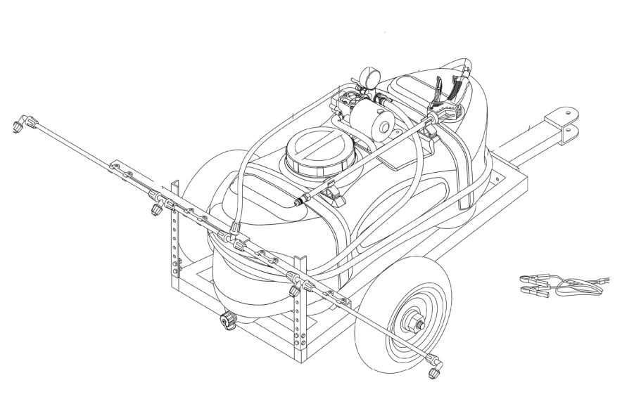
MaxBlast 60/100L ATV Sprayer & Trailer
This guide provides step-by-step instructions for assembling components and using your MaxBlast 60/80L ATV Sprayer & Trailer.
Product Information
The Maxblast ATV sprayer is designed for the spraying of pesticides, herbicides, growth regulators and liquid fertilizer. Mounted on a trailer and powered by the on-vehicle 12V power supply, the sprayer is equipped with a spray gun and a spray boom. It is easy to operate and maintain. It enables the cost effective spraying of large gardens or allotments. The high-quality diaphragm pump supplies a steady flow and high pressure. The pump is fitted with a pressure limiting switch for protection. Running without water for a short time is allowed, to prime the pump and shut the pump down if the tank runs dry. The chemical tank made of high-density polyethylene plastic ensures rigidity and resistance to pesticide corrosion. Because of the design of the system the tank is not pressurised. Two-step filtration is fitted to prevent blockages of the spray gun or spray boom.
| SKU | 26900 | 26901 |
|---|---|---|
| Capacity | 60L | 100L |
| Pump type | Diaphragm Pump | |
| Max Pump Press | 9 Bar | |
| Rated Voltage | 12V DC | |
| Motor Power | 65W | |
| Power Cord Length | 5m | |
| Spray Gun Press | 5.5 Bar | |
| Spray Gun Flow | 2.1L/min | |
| Spray Boom | 4.5 Bar | |
Safety Information
Safety Advice
Please read through the Safe Working Practice to ensure prevention of injury or damage to the device.
- Use the sprayer only for its intended purpose and only with liquids suitable for spraying.
- Follow all safety, handling, PPE and disposal instructions provided by the manufacturer of any chemical or liquid being used.
- Keep children, pets and unauthorised persons away from the sprayer during operation.
- Ensure the sprayer is correctly assembled and securely mounted to the ATV or vehicle before use.
- Check all hoses, fittings, straps, nozzles and electrical connections before each use. Do not use the sprayer if damaged, leaking or insecure.
- Connect the 12V power supply with the correct polarity and disconnect the power before cleaning, adjustment or maintenance.
- Do not sit, stand or place excessive loads on the sprayer.
- Check the terrain, slopes and surrounding area for hazards and obstacles before travelling or spraying.
- When using the spray boom, do not exceed 8 km/h.
- Avoid spraying in strong winds or where spray drift could affect people, animals, neighbouring property, watercourses or other unintended areas.
- Never point the spray gun or nozzles towards yourself or another person.
- Do not open, disconnect or adjust pressurised hoses or fittings until the pump has been switched off and pressure has been released.
- The diaphragm pump may run dry briefly for priming only. Do not operate it dry for extended periods.
- Do not leave chemicals or other liquids stored in the tank after use.
- After use, empty and clean the tank, hoses, filters and nozzles in accordance with the liquid manufacturer’s instructions and applicable disposal requirements.
- Never immerse the diaphragm pump or electrical components in water.
- Store the sprayer empty, clean and dry in a secure, well-ventilated location away from children and incompatible chemicals.
GPSR Information
UK GPSR Information
Monster House 19-23 Alan Farnaby Way
Industrial Estate Sheriff Hutton
York YO60 6PG
England
+441347878880
Monster House 19-23 Alan Farnaby Way
Industrial Estate Sheriff Hutton
York YO60 6PG
England
+441347878880
EU GPSR Information
Van Heemskerckweg 28A & B
-
Venlo 5928LL
Netherlands
+441347878880
Van Heemskerckweg 28A & B
-
Venlo 5928LL
Netherlands
+441347878880
Included Parts
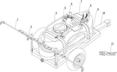
Monster Manual
Diagram
- Spray lance
- Beam
- Connection hose
- Diaphragm pump
- Pressure Gage
- Tank
- Adjustable Spray lance
- Outlet hose
- Chassis Frame
- Power cord
Assembly
- Choose a level, clean work area with enough room to move around the chassis.
- Have the diagrams visible while assembling.
- Do not fill the tank with chemicals during assembly or initial testing. This product requires a water trial before its first chemical use.
- Place the Chassis on a stable surface with the front/tow end accessible.
- Position the Traction Frame at the front of the Chassis.
- Align the two mounting holes.
- Fit 2 x M8x60 bolts with flat washers, spring washers and M8 nuts.
- Install both sides before tightening so the frame remains square.
- Bring the two sides down evenly and check that the Traction Frame is centred on the Chassis.
- Position the Upright Posts, one at each rear-side mounting location on the Chassis.
- Fit the M8x15 Hexagon Bolts with flat washer 8, spring washer 8 and M8 nut.
- Use the six fastener positions visible in the exploded diagram.
- Leave the Bolts just loose enough to allow the final alignment until the beams are fitted.
- Position the 2 x Beams between/on the upright posts as shown in the video and diagram.
- Use the M8x15 bolts with flat washer 8, spring washer 8, and M8 nuts to fix into place.
- Set the beam height for the intended spraying arrangement. The beams must be parallel to the ground.
- Check both beams are at the same height and are level side-to-side before the final tightening.
- Fit the Metal Connections to the Beams.
- Use M5x15 bolts , flat washers 5, spring washers 5 and M5 nuts to fix into place.
- Keep the nuts and bolts loose at first, align the Metal Connection so the Lance Clamps can sit squarely, then tighten.
- Position the Spray Lance Clamps onto the Metal Connections.
- Use the M5x15 bolts, flat washers 5, spring washers 5 and M5 nuts.
- Install both clamp positions and check that the clamp grooves are aligned with the intended lance position.
- Tighten to secure the structure. Do not over-tighten, this can deform the clamp brackets.
NOTE: The preferred nozzle heights are 50cm for herbicide/soil treatment and 30cm for insecticides, fungicides and growth regulators. These are guidelines for use.
- Thread the wheel shaft through the Chassis as shown in the drawing and video.
- Slide each Wheel over the wheel shaft.
- Fix into place using the flat washer 16, spring washer 16 and M16 hex nut to each side.
- Tighten both wheel fixings evenly. Confirm both wheels rotate freely without side-to-side movement.
NOTE: Keep the tank empty until the boom, gun, valves, hose and electrical connections have been completely checked.
- Place the Chemical Tank onto the Chassis frame, centred on the support rails.
- Align the tank base fixing points with the corresponding chassis holes.
- Fix into place using the provided bolt, flat washer and spring washer. Install from underneath the chassis into the tank base mounting points.
- Route the tie-down straps around the grooved sections of the tank and underneath the chassis.
- Press the assembled Four-nozzle Spray Lance into the groove of the support clamp on the Beam.
- Arrange the four nozzles so their outlets are on the same plane and directed outward as intended.
- Adjust the spray-fan direction so the spray fans are approximately 5-10 degrees relative to the lance to reduce spraying onto the chassis and direct more spray to the target area.
- Confirm the complete lance is parallel to the ground when the trailer is in operation.
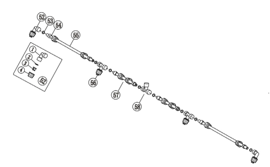
- Use the supplied O-rings, nozzle gaskets, fan nozzles, nozzle caps, fastening sleeves and metal connections as shown below.
- Ensure each sealing component is seated flat and not pinched.
- Begin fitting all nozzle and fitting threads by hand, before tightening with the provided spanners to avoid cross-threading.
- Check all four nozzles are aligned consistently. Replace or clean any damaged sealing component before the first chemical test.
- Connect the Spray Lance Feed Hose to the smaller shut-off valve on the diaphragm pump.
- Secure the hose connection with the supplied stainless-steel hose clamp.
- Keep the hose routed so it is not kinked, crushed by the chassis or likely to contact the wheels.
- Layout the outlet hose so it is not twisted.
- Connect one end of the outlet hose to the larger shut-off valve.
- Connect the other end of the outlet hose to the inlet of the adjustable spray gun.
- Secure both ends with stainless-steel hose clamps.
- Press the spray gun body into the holder/clamp on the tank when not in use.
NOTE: This is a dual shut-off arrangement. The larger valve supplies the spray gun; the smaller valve supplies the spray boom. The handles rotate through 90 degrees. With the red handle pointing toward the pump the valve is closed; when pointing toward the output pipe it is open. For routine operation, select the intended outlet by opening the appropriate shut-off valve. Keep the unused outlet closed to avoid unintended spraying.
- Confirm the pump cable connector is accessible and dry.
- Connect the supplied power cable to the pump lead.
- Connect to a suitable fused 12VDC vehicle supply, observing correct polarity.
- Route the 5m power lead away from the wheel path, tow connection and sharp chassis edges.
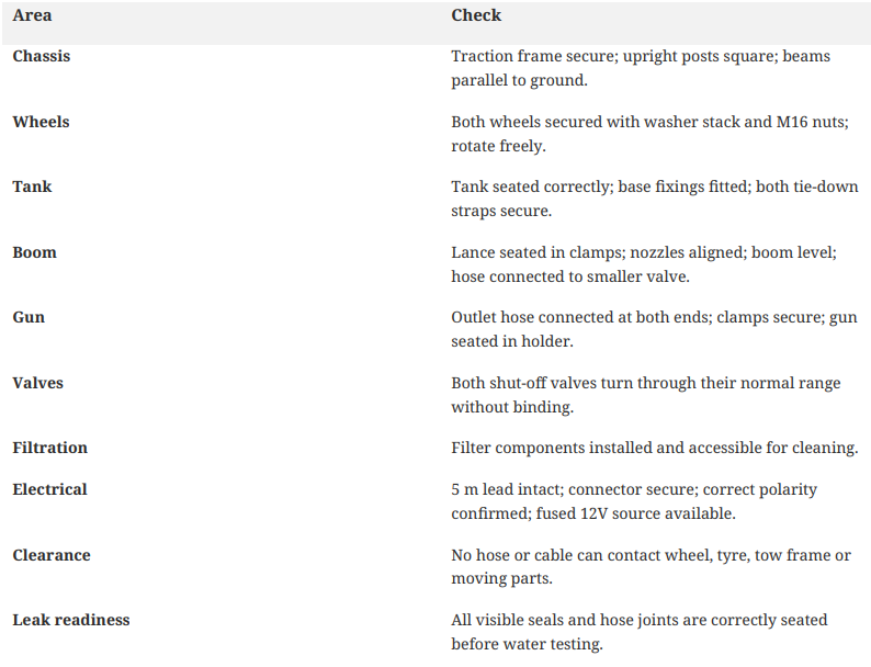
Before First Use
This product requires a trial spray with water before first use.
- Place the sprayer in a safe test area where clean water can be collected or disposed of appropriately.
- Close both shut-off valves.
- Fill the tank with clean water through the large strainer and secure the tank lid.
- Choose either the spray boom or spray gun outlet. Open only the selected outlet valve.
- Connect the power cable to a suitable fused 12VDC source.
- Listen for the change in pump sound as it primes and begins moving water through the hose.
- Close the chosen shut-off valve, the pump will stop.
- Inspect all hose joints, clamps, valves, filter connections and nozzle assemblies for leaks.
- Open the selected outlet again and confirm a consistent spray pattern.
- Disconnect the power, drain the test water and correct any leak or blockages found before chemical use.
Operating with the Spray Boom
- Confirm the water trial is successful and the system is leak-free.
- Prepare the intended chemical solution according to the product label/instructions.
- Close both shut-off valves before filling.
- Fill through the large strainer and tighten the tank lid securely.
- Confirm the boom valve is the selected outlet and the gun valve is closed.
- Connect the pump power lead to the 12V supply.
- Open the spray-boom shut-off valve to prime the system.
- Once the fluid is flowing and the system is primed, close the valve briefly. The pump will stop.
- Move the sprayer to the selected treatment area.
- Open the spray-boom valve to begin spraying.
- Keep the boom height and vehicle speed consistent. The vehicle should be moving no faster than 8km/h for level boom spraying.
- Watch the tank level and spray pattern continuously. Stop if the pattern becomes uneven, a hose leaks, or the pump behaves unexpectedly.
Operating with the Spray Gun
- Confirm the water trial is successful and the system is leak-free.
- Prepare the intended chemical solution according to the product label/instructions.
- Close both shut-off valves before filling.
- Fill through the large strainer and tighten the tank lid securely.
- Confirm the gun valve is the selected outlet and the boom valve is closed.
- Connect the pump power lead to the 12V supply.
- Open the spray-boom shut-off valve to prime the system.
- Once the fluid is flowing and the system is primed, close the valve briefly. The pump will stop.
- Move the sprayer to the selected treatment area.
- Open the larger shut-off valve.
- Depress the spray-gun trigger to begin spraying.
- Rotate the brass nozzle to vary the spray pattern from course to fine.
- Keep the hose clear of the wheels and tow frame while moving or repositioning.
After Use
- Disconnect the power source and close the selected shut-off valve, the pump will stop.
- If using the spray gun, depress the trigger to release line pressure.
- Remove the sprayer from the spraying area only after spraying has stopped.
- Empty any unused product and store it according to the manufacturer's instructions.
- Clean the tank with clean water.
- Flush the spray gun and spray boom with clear water after cleaning the tank.
- Inspect the filter(s), clean them as required to prevent blockages.
- Handle cleaning water as potentially contaminated with product residue and dispose of it in accordance with applicable requirements.
- Check that no hose has separated from a clamp.
- Check the spray-gun nozzle and each boom nozzle for residue.
- Confirm the two shut-off valves operate normally.
- Allow components to drain/dry as appropriate before storage.
- Do not leave product sitting in the tank.
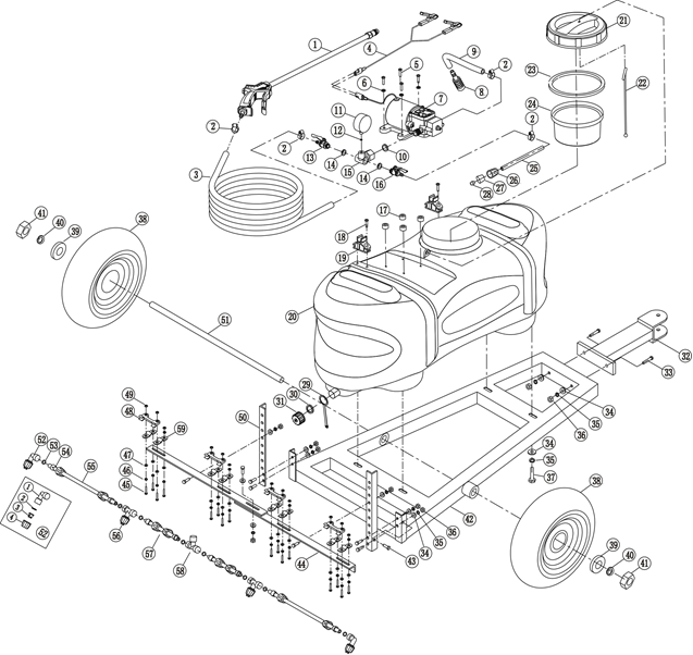
Exploded Diagram
1 - Adjustable Spray Gun
2 - Stainless Steel Clamp
3 - Outlet Hose
4 - Power Cord
5 - Screw M5X20
6 - Flat washer 5
7 - Diaphragm pump
8 - Filter
9 - Suction hose
10 - Pump opening gasket
11 - Manometer
12 - Seal
13 - Big opening shut-off valve
14 - Valve seal
15 - Cross Tee assembly
16 - Small opening shut-off valve
17 - Damping sleeve
18 - Screw set M5X16,
19 - Spray lance clamp
20 - Chemical tank
21 - Tank lid
22 - Anti-release rope
23 - Seal ring
24 - Big filter
25 - Connection hose
26 - Spray lance nut
27 - Tube sleeve
28 - Protection sleeve
29 - Anti-release belt
30 - Flat washer
31 - Bleeder
32 - Traction frame
33 - Hex bolt M8x60
34 - Flat washer 8
35 - Spring washer 8
36 - Hex nut M8
37 - Stainless steel screw bolt 5/16-18x16
38 - Wheel
39 - Flat washer 16
40 - Spring washer 16
41 - Hex nut M16
42 - Chassis
43 - Hex bolt M8x15
44 - Beam
45 - Hex bolt M5x15
46 - Spring washer 5
47 - Flat washer 5
48 - Spray lance clamp
49 - Hex nut M5
50 - Upright Post
51 - Wheel shaft
52 - Square nozzle
52.1 - Square Bend
52.2 - Nozzle gasket
52.3 - Fan nozzle
52.4 - Nozzle cap
53 - O-ring Φ15X3
54 - Fastening sleeve
55 - Long Spray Lance
56 - T-nozzle
57 - Short spray lance
58 - Tee
59 - Metal connection
Maintenance
Routine maintenance after each use
- Flush the tank, spray gun and boom with clean water.
- Inspect filters and clean out residue before it dries.
- Check hose clamps and visible fittings for signs of leakage or loosening.
- Check wheels and structural fasteners for looseness or damage.
- Inspect the power lead for cuts, crushed sections or damaged connectors.
Before storage
1. Empty the tank completely; do not store product in the sprayer.
2. Flush all fluid paths with clean water and dispose of cleaning water responsibly.
3. Allow hoses and outlets to drain as far as practical.
4. Store the sprayer in a safe place away from children and unauthorised users.
5. Keep the power cable dry and protected from mechanical damage.
Transport readiness
- Confirm the tank is empty unless the product instructions and transport requirements explicitly allow otherwise.
- Confirm the tank tie-down straps are secure.
- Confirm boom and gun are supported and cannot swing into the wheels or tow frame.
- Protect hoses and electrical cable from snagging on the vehicle or trailer hardware.
- Use the towing vehicle/trailer requirements applicable to your ATV and local rules; the supplied manual does not specify a separate trailer towing limit.
Troubleshooting
A: Check 12V source, 10A fuse, cable connections and polarity. Measure voltage at the vehicle-side clips and pump-side connector. If there is no issues with the supply, repair/replace cable or contact support.
A:The dual shut-off valve handles should rotate 90 degree. A seized valve needs replacement. Do not force the handle; replace or contact support.
A: Check the individual nozzles and feed hose. Clean the affected nozzle(s) and inspect the feed path.
It is likely that there is a blockage in the system. To avoid reoccurrence, ensure you flush out the spray boom and gun with clean water after use.
If both gun and boom appear blocked:
- Fill the tank with clean water and position the sprayer in a suitable safe place.
- Disconnect the two outlet pipes from the dual shut-off valve.
- Open the valves and visually check that you can see through the valve body.
- If clear, connect 12V power and confirm water exits both sides of the valve body.
- If water does not issue, inspect the pump feed pipe and filter; disconnect and flush the feed pipe with water.
If the gun is blocked, but the boom is working:
- Disconnect the feed pipe at the gun end and test flow from the pipe.
- If no water issues, disconnect the pipe from the shut-off valve and test again.
- If the valve has flow but the pipe does not, flush/clear the pipe and reconnect.
- If the pipe has flow but the gun does not, remove the brass spray-adjuster nozzle and use the flushing procedure described in the source manual, taking care to control water discharge.
If the boom is blocked, but the gun is working:
- Disconnect the feed pipe at the boom and test whether water issues from the pipe.
- If no water issues, disconnect the pipe at the shut-off valve and flush the pipe.
- Confirm water issues from the shut-off valve while the pipe is disconnected.
If only some boom nozzles are blocked:
- Identify the individual nozzle(s) not spraying.
- Remove the affected nozzle assembly as described in the manual above.
- Clean the nozzle and sealing components. Blocked individual nozzles can be removed and cleaned and may also be replaced using supplied spares.
- Reinstall and perform a clean-water spray test before returning to chemical spraying.