Monster Manuals|
Cover

T-MECH Mini Lathe

This guide provides step-by-step instructions for assembling components and using the T-MECH Mini Lathe.
Product Information

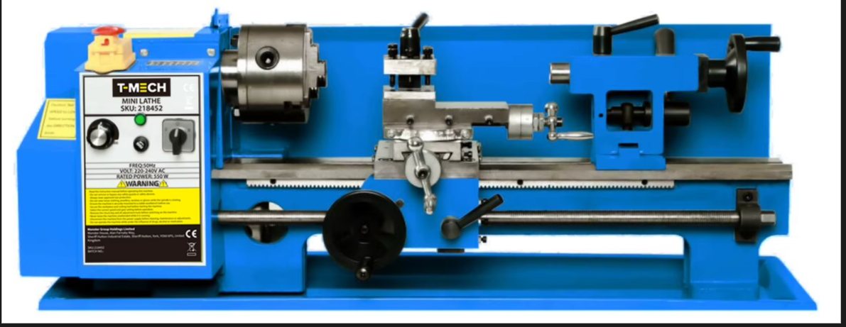
The Mini Metalworking and Woodworking Lathe is a compact yet powerful 550W bench-mounted machine designed for precision turning, facing, drilling, threading and shaping of compatible metal, wood and plastic workpieces. Featuring variable spindle speeds from 0–2,500 RPM, a rigid cast iron construction and durable metal gearing, it delivers accurate and reliable performance. Supplied with essential accessories including turning tools, chuck wrench, reverse chuck jaws, gears, oil pot and tool kit, it provides everything required to begin machining.

SKU 218452
Dimensions 765*300*290mm
Voltage 240V
Motor Power 550W
Centre Distance 350mm
Chuck Diameter 100mm
Spindle Speed 0-2500±10%
Thread range 0.5-3mm
Gear Material Metal

Safety Information

Safety Advice

• Ensure you have read and fully understood the instruction manual and safety advice before using this product. 
• Package contents: 1 × mini lathe, 3-jaw chuck, turning tools (5 pcs), chuck wrench, reverse chuck jaws (1 set), spare gears (9 pcs), 2 × screwdrivers (flat and PH2), 5 × hex keys, 3 × double open-ended spanners, oil pot, plastic tool box, rubber feet and instruction manual. 
• This product is intended solely for machining compatible metals, wood and suitable plastics using appropriate cutting tools and accessories. 
• Do not use this product for grinding, cutting masonry, processing hazardous materials or any purpose other than its intended use. 
• This product is intended for use by competent adults only. 
• Keep children, pets and unauthorised persons away from the work area at all times. 
• Assemble the machine fully before use and ensure all components are correctly installed and securely tightened. 
• Secure the lathe to a rigid, level workbench using suitable fixings before operation. Never operate the machine unsecured. 
• Ensure sufficient lighting and keep the work area clean, dry and free from trip hazards. 
• Inspect the machine, power cable, plug, chuck, tooling, guards and controls before each use. Do not use the machine if any component is damaged, loose or excessively worn. 
• Ensure the mains supply matches the voltage specified on the machine rating plate. 
• Never use the machine in wet or damp environments. 
• Ensure all guards and covers are correctly fitted before switching on the machine. 
• Never operate the machine with the gear cover, chuck guard or any safety device removed or damaged. 
• Check that the workpiece is correctly mounted and securely clamped before starting the machine. 
• Always remove the chuck key immediately after tightening the chuck and before switching the machine on. 
• Rotate the chuck by hand before starting to confirm the workpiece clears the tool and machine bed. 
• Stand to one side during start-up until the machine reaches full operating speed. 
• Select the correct spindle speed, feed and tooling for the material being machined. 
• Keep hands, fingers and all parts of the body away from the rotating chuck, spindle, workpiece and cutting tool. 
• Never wear gloves whilst operating the lathe where there is a risk of entanglement with rotating parts. 
• Do not wear loose clothing, ties, jewellery or other items that could become caught in moving components. 
• Tie back long hair and avoid loose sleeves before operating the machine. 
• Always wear suitable eye protection during operation. 
• Wear suitable respiratory protection and use effective dust extraction when machining wood or other dust-producing materials. 
• Do not machine materials that produce toxic, flammable or explosive dust unless suitable extraction and control measures are in place. 
• Never attempt to stop the rotating chuck or workpiece by hand. 
• Never measure, adjust, clean or lubricate the machine whilst the spindle is rotating. 
• Switch off the machine and allow all moving parts to come to a complete stop before making adjustments. 
• Disconnect the machine from the mains supply before changing tooling, changing gears, adjusting belts, performing maintenance or cleaning. 
• Ensure the cutting tool is securely clamped and correctly positioned before machining. 
• Replace damaged, chipped or excessively worn cutting tools immediately. 
• Use only accessories and replacement parts suitable for this machine. 
• Be aware that workpieces, cutting tools and swarf may become extremely hot during machining. Allow components to cool before handling. 
• Never remove swarf by hand. Use a suitable brush or swarf hook only after the machine has stopped completely. 
• Handle sharp swarf carefully to avoid cuts and puncture injuries. 
• Keep the machine bed clear of swarf and unnecessary tools throughout use. 
• Take particular care when changing gears. Keep fingers clear of gear teeth and pinch points. 
• Never operate the machine with the gear cover removed following maintenance or gear changes. 
• Ensure adequate ventilation around the motor to prevent overheating. 
• Stop using the machine immediately if unusual vibration, excessive noise, overheating, smoke or burning odours occur. Disconnect the power supply and investigate the cause before further use. 
• Do not leave the machine running unattended. 
• Switch the machine off and isolate it from the mains supply after use. 
• Store accessories safely to prevent damage and accidental injury. 
• This product is not intended for commercial production environments unless suitable risk assessments, training and workplace safety measures are implemented. 
• Dispose of worn cutting tools, lubricants, electrical components and the machine itself in accordance with local environmental regulations. Do not dispose of electrical equipment with household waste. 
• Retain these instructions for future reference. 

GPSR Information

UK GPSR Information
Manufacturer Monster Group UK Limited
Monster House 19-23 Alan Farnaby Way
Industrial Estate Sheriff Hutton
York YO60 6PG
England
+441347878880
Representative Rana Harvey
Monster House 19-23 Alan Farnaby Way
Industrial Estate Sheriff Hutton
York YO60 6PG
England
+441347878880
EU GPSR Information
Manufacturer Monster Group BV
Van Heemskerckweg 28A & B
-
Venlo 5928LL
Netherlands
+441347878880
Representative Rana Harvey
Van Heemskerckweg 28A & B
-
Venlo 5928LL
Netherlands
+441347878880

Included Parts
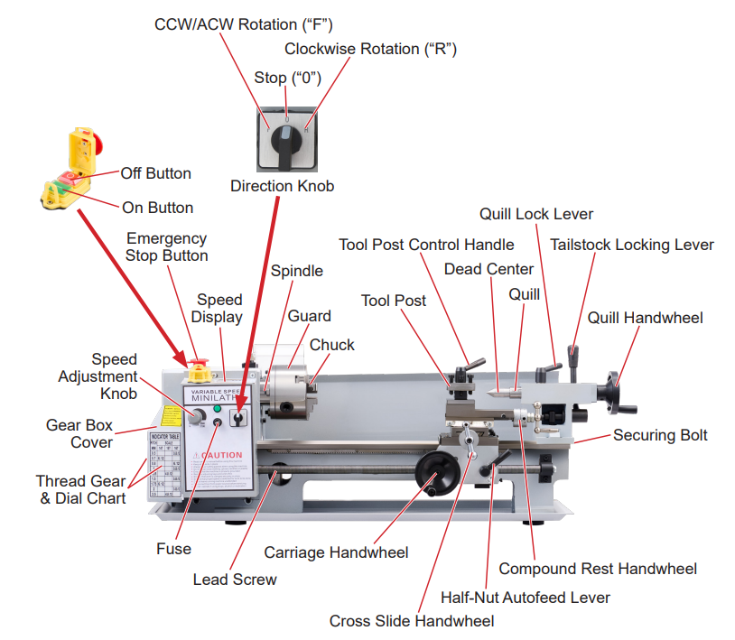
Parts Overview
1x Part 1 - Mini Lathe
5x Part 2 - Lathe Tools
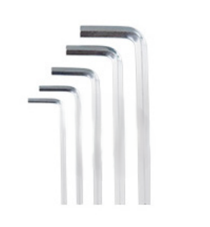
5x Part 3 - Hex Key Wrench (6mm, 5mm, 4mm, 3mm, 2.5mm)
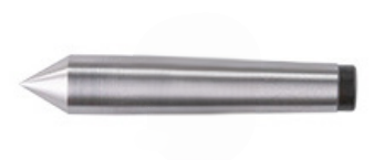
1x Part 4 - Dead Centre
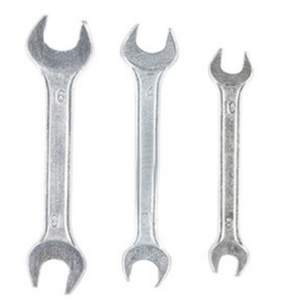
3x Part 5 - Double Open Wrench (13-16mm, 12-14mm, and 8-10mm)
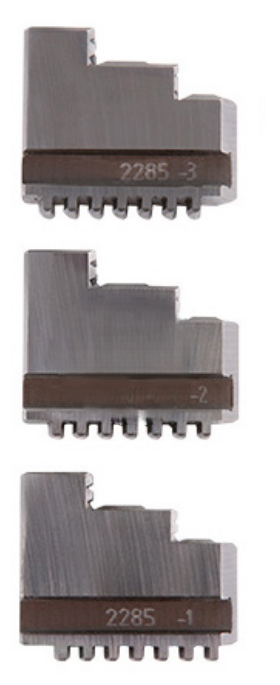
1 setx Part 6 - Forwards Chuck Jaws (3pcs)
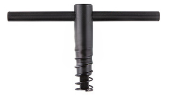
1x Part 7 - Chuck Wrench
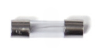
1x Part 8 - Spare Fuse
1x Part 9 - Bottle for Oil
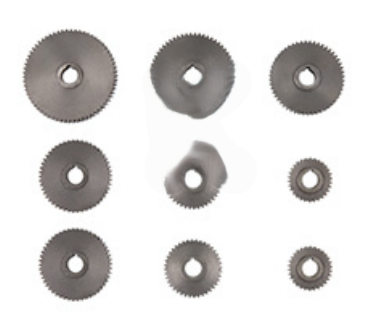
9x Part 10 - Metal Changing Gears (60toothx2pcs, 50toothx2pcs, 40toothx2pcs, 45toothx1pc, 35toothx1pc, 30toothx1pc)
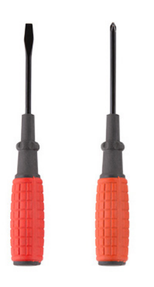
2x Part 11 - Screwdrivers (Flat Bit and PH2)
1x Part 12 - Base Tray
4x Part 13 - M6*16 Base Screws
4x Part 14 - Rubber Feet
1x Part 15 - Tailstock Clamping Block
1x Part 16 - Tailstock Nut
1x Part 17 - Tailstock
1x Part 18 - Quill Handwheel Handle
1x Part 19 - Cross Slide Handwheel Handle
1x Part 20 - Compound Rest Handwheel Handle
1 setx Part 21 - Reverse Chuck Jaws (3pcs)
1x Part 22 - Plastic Tool Box

Monster Manual

Assembly

1. Unbolting from Crate
NOTE: Clean all parts with a dry cloth before first use to remove protective oil.
  • Remove the accessories from the crate.
  • Flip the crate and unbolt the 4 screws on the wooden base from the Mini Lathe (Part 1).
NOTE: Use 2 or more people to move the Mini Lathe and always move holding the main body, not the components.

2. Attaching Base Tray
  • Place the base tray (Part 12) face down on the Mini Lathe.
  • Place the rubber feet (Part 14) over the bolt holes in the base tray.
  • Attach the base screws (Part 13) until secure.
  • Flip the Mini Lathe into position.
3. Mounting the Tailstock
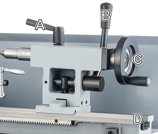
  • Undo the securing bolt (D) on the right hand side of the Mini Lathe (Part 1).
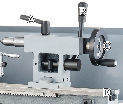
  • Lay the Tailstock on its side and place the Tailstock Clamping Block (Part 15) over the threaded rod that sits on the underside of the Tailstock.
  • Loosely thread the Tailstock Nut (Part 16) on to the threaded rod.
  • Ensuring the Tailstock Locking Lever (B) is pulled up, slide the Tailstock (Part 17) onto the Lathe Bed.
  • Move the Tailstock (Part 17) to the centre of the Lathe Bed.
  • Reach under the Tailstock (Part 17) and tighten the Tailstock Nut (Part 16) until secure.
  • Reinsert the securing bolt (D) on the right hand side of the Mini Lathe (Part 1).
NOTE: The Tailstock can be removed, if desired.
Step 3 Image 1
4. Attaching the Dead Centre to the Quill
  • Release the Quill Locking Lever (A), insert the Dead Centre (Part 4) into the Quill.
  • Lock the Quill Locking Lever (A) back into place.
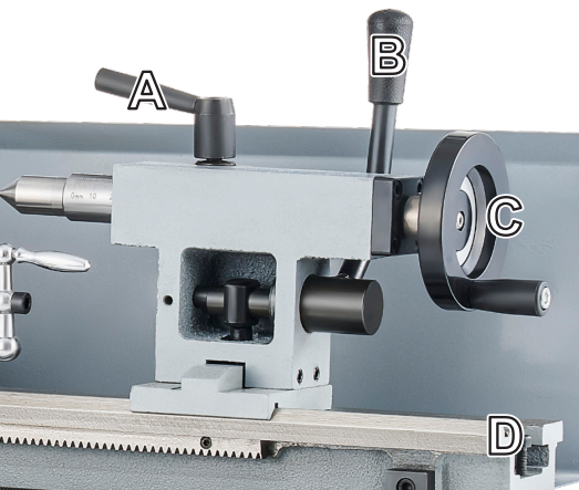
NOTE: The supplied Dead Centre can be replaced with any compatible Morse taper accessory (not included).
Step 4 Image 1
5. Attaching Other Components
  • Attach the Quill Handwheel Handle (Part 18) (not pictured below) to the Quill Handwheel by screwing the handle onto the female threaded stud until secure.
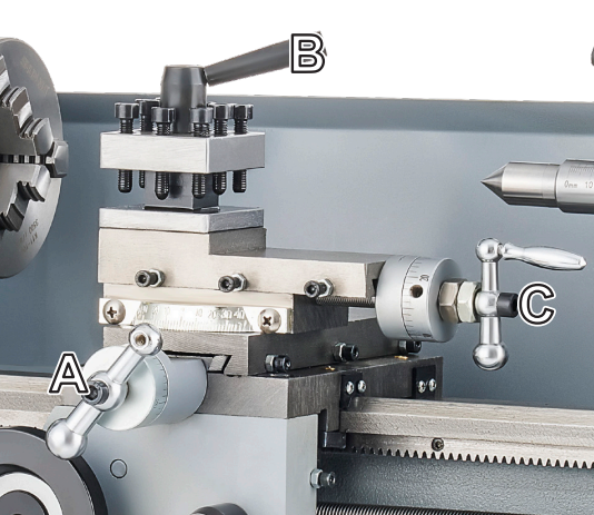
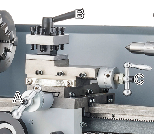
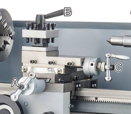
  • Attach the Cross Slide Handwheel Handle (Part 19) to the Cross Slide Handwheel (A) by twisting the handle onto the female threaded stud until secure.
  • Attach the Compound Rest Handwheel Handle (Part 20) to the Compound Rest Handwheel (C) by twisting the handle onto the female threaded stud until secure.
Step 5 Image 1
6. Attaching the Tool Post and Handle
  • Place the Tool Post onto the Carriage and secure into place.
Step 6 Image 1
7. Switching between Forward and Reverse Jaws
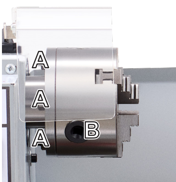
  • Insert the Chuck Wrench (Part 7) into the Chuck Hole (B) and rotate anti-clockwise until the jaws are in their widest position.
  • Look for the numbers engraved on the jaws and remove the jaws in reverse order (3->2->1).
  • Mount the new jaws in order, starting with Jaw 1 that must be inserted into the section of chuck with the engraved "1". Working clockwise, insert Jaw 2 and Jaw 3. The jaws must be inserted and held firmly into position before tightening the chuck.
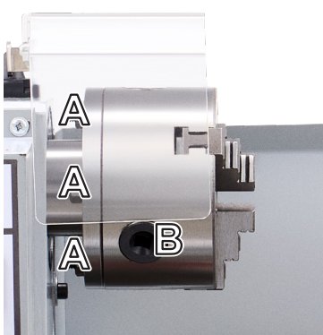
NOTE: The jaws are engraved with a code to identify the jaw direction. Reverse Jaw: 7807; Forward Jaw: 3687.
Step 7 Image 1

Set-Up/Adjustments

1. Adjusting Tailstock into Position
  • Lift the Tailstock Locking Lever (B) and slide the Tailstock along the Lathe Bed until it reaches the end of the workpiece
  • Push the Tailstock Locking Lever (B) down to lock the Tailstock into place
  • Rotate the Quill Locking Lever (A) to unlock the Quill and Dead Centre (or other attached tool) into place
  • Rotate the Quill Handwheel (C) to move the Dead Centre to the workpiece until it makes light contact with the workpiece
  • Rotate the Quill Locking Lever (A) to lock the Quill and Dead Centre (or other attached tool) into place
Step 1 Image 1
2. Mounting the Tool(s)
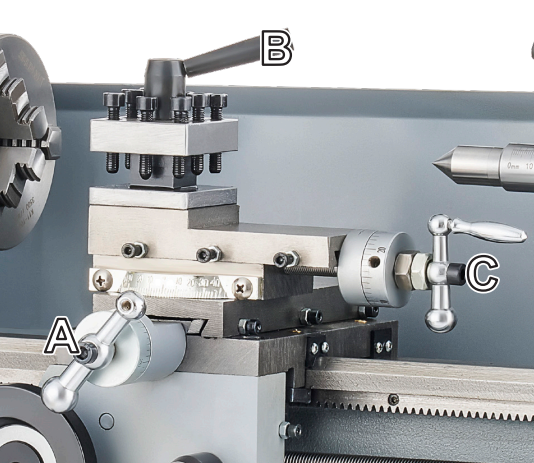
  • Loosen the bolts at the top of the Tool Post using an Allen Key.
  • Insert your tools into the Tool Post; add any shims to ensure the tool is centred.
  • Tighten the bolts at the top of the Tool Post until the tool is secure.
NOTE: You can insert up to 4 tools in the Tool Post. One on each face of the Tool Post
  • To switch between tools, rotate the Tool Post Control Handle (B) until the Tool Post can easily move. Twist the Tool Post in the desired direction and relock using the Tool Post Control Handle (B).
Step 2 Image 1
3. Moving the Tool(s)
General Movement of the Carriage:
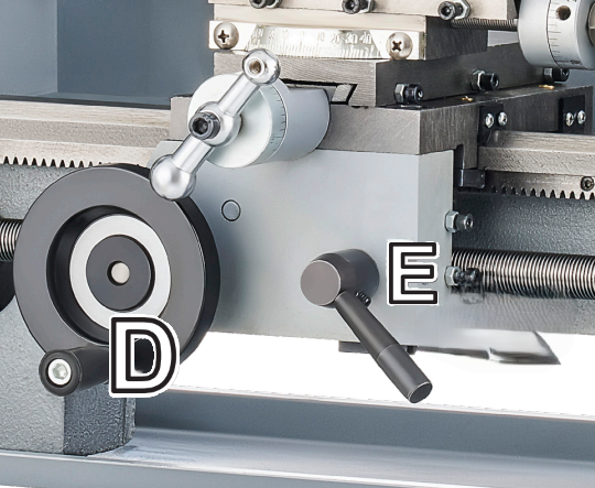
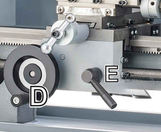
  • Turn the Carriage Handwheel (D) to manually move towards the headstock or tailstock.
NOTE: Ensure the Automatic Feed (E) is disengaged.

Precise Movement of the Carriage:
  • Turn the Cross Slide Handwheel (A) to move the Tool Post inward or outward.
  • Turn the Compound Rest Handwheel (C) to move your tool towards the headstock or tailstock in controlled motions.
Step 3 Image 1
Step 3 Image 2
4. Activating the Automatic Feed
  • Move the Automatic Feed Lever (E) down to engage the Mini Lathe's Autofeed.
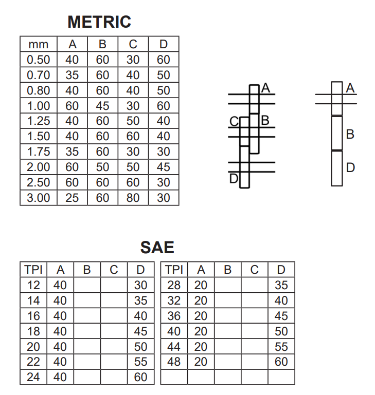
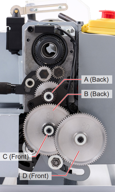
  • Once the lead screw is turning, the carriage will automatically follow the direction set by the Autofeed Direction Knob at the speed set by the Changing Gear (Part 10) and the Autofeed Speed Knob.
  • Move the Automatic Feed Lever up to disengage the Autofeed.
NOTE: Use the thread chart to prepare the correct Change Gears before use. Be aware of the following:
1. A blank space indicates that no gear is needed.
2. Numbers like "55" and "60" refer to the gears with 55 and 60 teeth.
3. The 20, 45, and 80-tooth gears were preinstalled at the factory.

NOTE: Always disengage the Autofeed after use to prevent unexpected movement and accidents during your next session.

Step 4 Image 1
Step 4 Image 2
Step 4 Image 3

Using the Mini Lathe

1. Setting Up
Check that:
  • the gears are correct for any work with the Autofeed
  • the direction knob is set to 0
  • the speed dial is set to 0 rpm
  • the Autofeed direction lever is set correctly; up for forward movement towards the headstock or down for reverse movement towards the tailstock
  • the correct tools are inserted into the Tool Post
  • any other desired adjustments have been made
NOTE: Before connecting to power, ensure you are wearing protective eyewear and any other necessary PPE.

  • Connect to power, raise the emergency stop button, close the safety guard and press the "ON" button.
  • Set the direction knob to make the workpiece turn clockwise "R" or anti-clockwise "F"
WARNING: Setting the direction knob and Autofeed in different directions can produce dangerous backlash.
  • Set the speed dial to your desired rotation.
WARNING: ALWAYS use the emergency STOP if any accident occurs. Dialling the speed down or making other adjustments will NOT immediately stop the spindle or Autofeed.
2. Securing the Workpiece into the Jaws
NOTE: When making adjustments to the device, ensure the power is set to OFF, the direction is set to STOP, the speed is set to ZERO and the device is unplugged, see Step ?
  • Place the Chuck Wrench (Part 7) into the Chuck Hole (B) and rotate until the jaws are slightly larger the workpiece. Rotate anti-clockwise to tighten the jaws. Rotate clockwise to loosen the jaws.
  • Place the workpiece into the jaws and then tighten the jaws (twist the Chuck Wrench anti-clockwise) around the workpiece until it is holding securely.
  • For longer pieces, move the tailstock towards the Chuck until the workpiece is securely fixed against the dead centre.
  • For metal, the piece should usually not extend from the Chuck further than 3 times its diameter without other support.
Step 2 Image 1
3. Cutting
NOTE: ALWAYS ensure the workpiece is held firmly in place before cutting.
Standard Cutting:
  • Use either the Autofeed or the manual feed to move the tool against the rotating outer surface of the workpiece.
Face Cutting:
  • Mount your tool so that it faces the headstock.
  • Use the manual feed on the Carriage to press the tool into the face of the workpiece.
Internal Cutting
  • Rotate the tool post so that the cutter is placed in the middle of the front face of the workpiece.
Bevel Cutting:
  • Adjust the angle of the Tool Post to cut bevels into the workpiece.
Thread Cutting:
  • Lathe your workpiece to the correct outer diameter.
  • Set the Change Gears to produce the correct speed for your desired pitch.
  • Use a tool exactly the size of your thread mounted in line with the centre of the workpiece.
  • Run the feed as slowly as possible. Engage the Autofeed and produce your first pass.
  • At the end of the pass, turn off the motor while backing your tool away from the workpiece.
WARNING: When switching between F and R, ALWAYS pause and allow the spindle to come to a complete stop before restarting. Failure to do so may damage the main control board and result in loss of speed control.
  • Reverse the spindle and Autofeed direction using the direction knob and the lever behind the lathe's gearbox.
  • Restart the motor to automatically move the tool back to its original position.
  • Alternate moving the top slide about 0.2-0.3mm left and right with each pass. Repeat the process until you have the desired threading. Produce a chamfer at the head of the thread and undercut at its runout.
4. When you are finished
  • Turn the speed to 0 rpm, the spindle direction to 0, press the OFF button and disconnect the lathe from power. Be sure to disengage the Autofeed if it is on.
  • Remove the workpiece and clean any swarf, dust, or debris from your machine.

Maintenance

Regularly inspect all fasteners, guards, gears, bearings, electrical components, power cable, chuck and tooling for signs of wear or damage. Keep the machine clean and free from swarf, lubricate all recommended moving parts using suitable machine oil, replace worn gears and cutting tools as required, and periodically check chuck accuracy, belt condition and mounting security. Always disconnect the machine from the mains supply before carrying out inspection, cleaning, lubrication or maintenance.

Troubleshooting

Please read through the guide below if you have any issues or faults with your device. The information covers and resolves the majority of frequently asked questions.
Q: There are parts missing from my order.
A: If there appears to be any part missing from your order, contact our friendly and helpful Customer Support Team within 7 days of receipt.
For all other issues please contact our Customer Support department via the details on the Contact page.